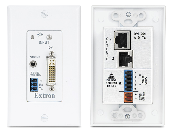
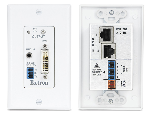
| DVI 201 A D Tx/Rx |
| NOTE |
*Appropriate DVI-D to HDMI cables or adapters are required for HDMI signal input/output.
Also, an optional Extron HDMI-to-DVI adapter is required in order to transmit a CEC signal. | |
|
| Video |
| Maximum data rate |
4.95 Gbps (1.65 Gbps per color) |
| Maximum pixel clock |
165 MHz |
| Resolution range |
1920x1200 or 1080p @ 60 Hz |
| Formats |
RGB and YCbCr digital video |
| Standards |
DVI 1.0, HDMI 1.2 |
|
| Video input and loop through — transmitters |
| Number/signal type |
1 single link DVI-D (or HDMI*) input
1 single link DVI-D (or HDMI*) local loop-through |
| Connectors |
|
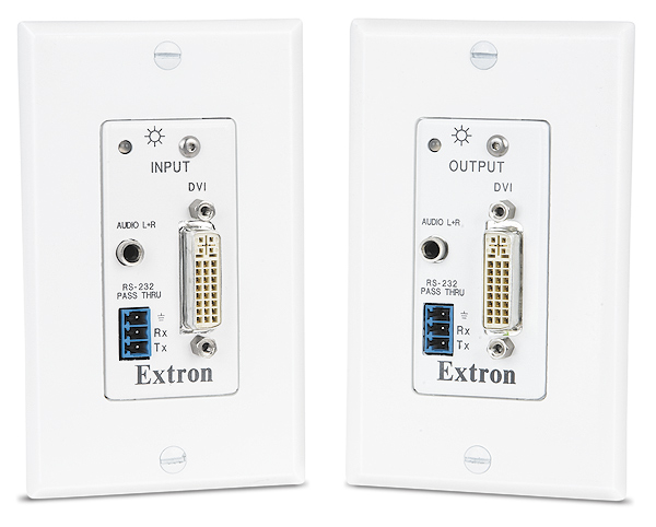
| DVI 201 A D Tx |
1 female DVI-I |
|
| Interconnection between transmitter and receiver |
| Connectors |
2 female RJ-45 per unit for 2 cables connecting the transmitter and receiver |
| Termination standards |
TIA/EIA T568A or T568B |
| Signal transmission distance |
|
| 1920x1200 or 1080p @ 60 Hz |
| Extron DTP26 cable |
Up to 150' (45 m) |
| CAT 5/5e/6 STP |
Up to 125' (38 m) |
| CAT 5/5e/6 UTP |
Up to 100' (30 m) |
| 1024x768 or 720p/1080i @ 60 Hz |
| CAT 5/5e/6 UTP or STP or Extron DTP26 |
Up to 200' (60 m) |
| NOTE |
The transmission distance varies greatly depending on the signal resolution and on the type of cable, graphics card, and display used in the system. | |
|
| Video output — receivers |
| Number/signal type |
1 single link DVI-D (or HDMI*) |
| Connectors |
|
| DVI 201 A D Rx |
2 female DVI-I |
|
| Audio |
| Gain |
Unbalanced output: 0 dB; balanced output: +6 dB |
| Frequency response |
20 Hz to 20 kHz, ±0.05 dB |
| THD + Noise |
0.10% @ 1 kHz at nominal level |
| S/N |
>85 dB at maximum output (unweighted) |
| Stereo channel separation |
>86 dB @ 1 kHz |
|
| Audio input |
| Number/signal type |
|
| DVI 201 A D Tx |
1 stereo, unbalanced |
| DVI 201 A D Rx |
1 stereo, balanced/unbalanced |
| Connectors |
|
| DVI 201 A D Tx |
(1) 3.5 mm mini audio jack (tip, ring, sleeve) |
| DVI 201 A D Rx |
(1) 3.5 mm captive screw connector, 5 pole |
| Impedance |
|
| DVI 201 A D Tx |
>10k ohms unbalanced, DC coupled |
| DVI 201 A D Rx |
>18k ohms unbalanced, 14k ohms balanced, DC coupled |
| Nominal level |
|
| DVI 201 A D Tx |
-10 dBV (316 mVrms) |
| DVI 201 A D Rx |
+4 dBu (1.23 Vrms) |
| Maximum level |
|
| DVI 201 A D Tx |
+11 dBu, unbalanced at 1% THD+N |
| DVI 201 A D Rx |
+16.8 dBu, unbalanced at 1% THD+N |
| NOTE |
0 dBu = 0.775 Vrms, 0 dBV = 1 Vrms, 0 dBV ≈ 2 dBu | |
|
| Audio output |
| Number/signal type |
|
| DVI 201 A D Tx |
1 stereo, balanced/unbalanced |
| DVI 201 A D Rx |
1 stereo, unbalanced |
| Connectors |
|
| DVI 201 A D Tx |
(1) 3.5 mm captive screw connector, 5 pole |
| DVI 201 A D Rx |
(1) 3.5 mm mini audio jack (tip, ring, sleeve) |
| Impedance |
|
| DVI 201 A D Tx |
50 ohms unbalanced, 100 ohms balanced |
| DVI 201 A D Rx |
50 ohms unbalanced |
| Maximum level (Hi-Z) |
|
| DVI 201 A D Tx |
>+16 dBu, balanced or unbalanced at 1% THD+N |
| DVI 201 A D Rx |
>+9.8 dBu, unbalanced at 1% THD+N |
| Maximum level (600 ohm) |
|
| DVI 201 A D Tx |
>+9 dBm, balanced or unbalanced at 1% THD+N |
| DVI 201 A D Rx |
>+6.8 dBm, unbalanced at 1% THD+N |
|
| Control/remote — external device (pass-through) |
| Serial control port input |
|
| Transmitter |
RS-232 via (1) 3.5 mm, 3 pole captive screw connector |
| Receiver |
1 set of proprietary signals on a female RJ-45 jack |
| Serial control port output |
|
| Transmitter |
1 set of proprietary signals on a female RJ-45 jack |
| Receiver |
RS-232 via a 3.5 mm, 3 pole captive screw connector |
| NOTE |
Protocol is mirrored between the transmitter and the receiver. | |
| Serial control pin configurations |
Captive screw connectors: 1 = TX, 2 = RX, 3 = GND |
|
| General |
| External power supply |
100 VAC to 240 VAC, 50-60 Hz, 6 W max., external; to 12 VDC, 1 A, regulated |
| Power input requirements |
12 VDC, 0.4 A for both transmitter and receiver |
| NOTE |
Each transmitter or receiver can be powered either locally by an external power supply or remotely by receiver or transmitter on the other end of the CAT 5/5e/6 or Extron DTP26 cable. | |
| Temperature/humidity |
Storage: -40 to +158 °F (-40 to +70 °C) / 10% to 90%, noncondensing
Operating: +32 to +122 °F (0 to +50 °C) / 10% to 90%, noncondensing |
| Cooling |
Convection, no vents |
| Mounting |
|
| Rack mount |
Yes, with optional 1U rack shelf |
| Furniture mount |
Yes, with optional through-desk mounting kit |
| Pole mount |
Yes, with optional mounting kit |
| Enclosure type |
Metal |
| Enclosure dimensions |
|
| Faceplate |
2.6" H* x 1.3" W x 0.1" D
(6.6 cm H* x 3.3 cm W x 0.3 cm D)
(Fits the opening in a 1 gang Decora®-style wallplate.)
*Overall height is 4.1" (10.4 cm) including mounting tabs. Mounting holes are 3.8" [9.5 cm] apart on center. |
| Buffer |
2.7" H x 1.8" W x 0.75" D
(6.9 cm H x 4.6 cm W x 1.9 cm D)
(Depth excludes connectors.) |
| Product weight |
0.5 lbs (0.3 kg) |
| Shipping weight |
3 lbs (2 kg) |
| Vibration |
ISTA 1A in carton (International Safe Transit Association) |
| Regulatory compliance |
|
| Safety |
CE, c-UL, UL |
| EMI/EMC |
CE**, C-tick, FCC Class A**, ICES, VCCI |
| NOTE |
**CE and FCC testing is conducted with STP (shielded twisted pair) cable. | |
| MTBF |
30,000 hours |
| Warranty |
3 years parts and labor |